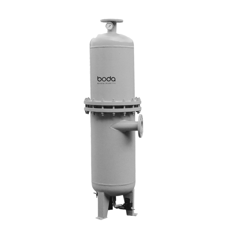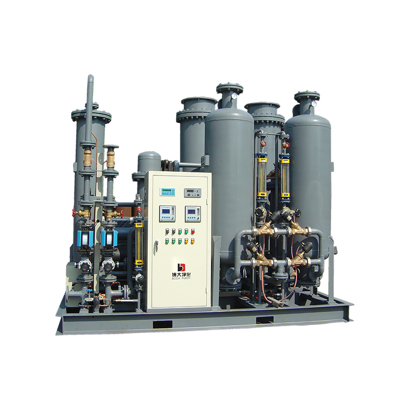
PSA nitrogen generators solve this by using pressure swing adsorption to separate nitrogen from compressed air. Compressed air passes through vessels packed with carbon molecular sieve (CMS), which adsorbs oxygen, carbon dioxide, and moisture. Nitrogen flows through, and the CMS is regenerated by releasing pressure. These systems are also known as BXN PSA nitrogen generation units, named for their twin-tower design.
The separation efficiency depends on the adsorption cycle, including purge timing and air quality. Understanding that cycle is the first step in sizing and maintaining a reliable on‑site supply.
How PSA Nitrogen Generators Work: The Adsorption Process
Pressure swing adsorption (PSA) separates nitrogen from compressed air using a physical process, not chemical filtration. The core principle is simple: oxygen and other trace gases are smaller molecules that fit into the micropores of carbon molecular sieve (CMS), while larger nitrogen molecules pass through.
The cycle alternates between two identical vessels to deliver a continuous nitrogen supply. Each vessel follows four stages:
- Adsorption – Compressed air enters the vessel at 6–10 bar. CMS preferentially adsorbs oxygen, carbon dioxide, and moisture. Product nitrogen exits at the set purity, typically 95% to 99.999%.
- Pressure equalisation – The pressurised vessel and a depressurised vessel are connected to balance pressure, conserving energy and improving recovery.
- Desorption (blowdown) – The vessel vents to near-atmospheric pressure. Adsorbed gases are released and purged out with a small nitrogen flow from the on‑line vessel.
- Purge and repressurisation – A fraction of product nitrogen purges the CMS bed, then the vessel repressurises with feed air for the next cycle.
Purity directly affects recovery rate: 99.5% nitrogen yields roughly 40–50% recovery from the feed air, whereas 95% can exceed 70%. Inlet air quality is critical – oil, water, or particulates degrade CMS capacity and accelerate replacement. Clean, dry compressed air (ISO 8573-1 Class 1.4.1 or better) is the standard recommendation from every nitrogen generator manufacturer.
Key Components and Their Roles in PSA Systems
The performance of PSA nitrogen generators depends on the quality of their core components. Each part directly affects purity, flow consistency, and overall reliability.
| Component | Function | Maintenance Tip |
|---|---|---|
| Compressor | Delivers compressed air at the required pressure and flow. | Replace air filters, oil filters, oil separators and lubricating oil regularly. |
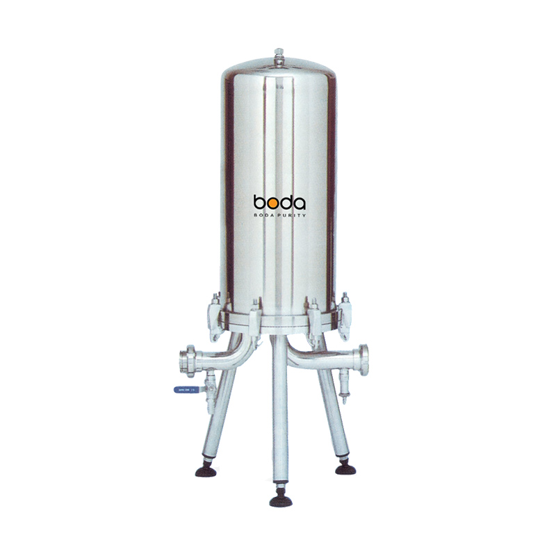
| Air treatment (dryer, filters) | Removes moisture, oil, and particulates to protect the carbon molecular sieve. | Replace prefilters annually; check dew point monthly. |
| Dual adsorption vessels (CMS) | One vessel adsorbs oxygen while the other regenerates. | Replace CMS every 6–10 years; inspect for contamination from oil or water. |
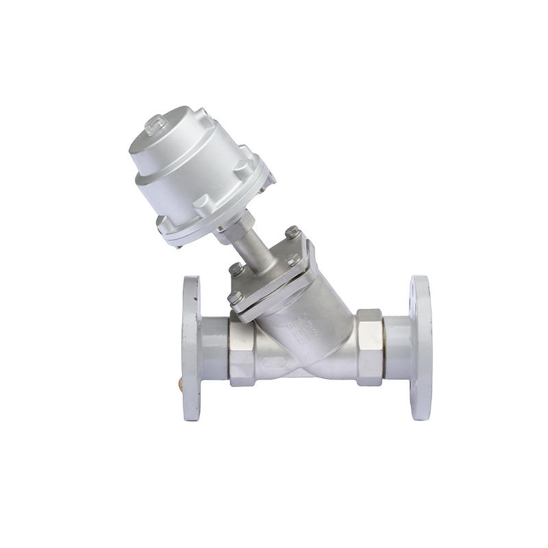
| Directional and purge valves | Control air flow and pressure cycling between vessels. | Test seals and solenoids quarterly; replace if leaks are detected. |
| Control system | Manages cycle timing, purity monitoring, and alarms. | Calibrate oxygen sensor yearly; update control logic if available. |
| Nitrogen buffer tank | Smoothes flow and ensures consistent supply pressure. | Drain condensate weekly; test relief valve annually. |
Common failure points stem from neglected maintenance: oil or moisture bypassing the air treatment, worn valve seals causing pressure loss, and sieve degradation from contamination. Addressing these issues proactively maintains the purity levels for which your PSA nitrogen generator was designed.
Comparing PSA and Membrane Nitrogen Generators for Industrial Applications
The primary decision factor between PSA and membrane technology is the trade-off between purity and operating cost. PSA nitrogen generators deliver high purity up to 99.999% but involve higher energy and maintenance demands. Membrane units offer simplicity and a compact footprint, though they typically cap purity at 99.9%.
Quick Comparison
| Factor | PSA Nitrogen Generator | Membrane Nitrogen Generator |
|---|---|---|
| Purity range | Up to 99.999% | Typically up to 99.9% |
| Flow rate flexibility | Variable responds well to demand changes | Best at stable, constant flow |
| Energy consumption | Lower energy consumption at high purity (above 99%). | For medium- to low-purity requirements, the initial investment for membrane separation equipment is generally lower |
| Footprint | Larger (twin adsorption vessels, buffer tank) | Compact, modular design |
| Maintenance frequency | Low – periodic filter changes only | Low – periodic filter changes only |
| Total cost of ownership | Higher upfront cost; lower per m³ at high purity | Lower upfront; higher per m³ above 99.5% |
When to Choose PSA
Go with PSA when your process demands nitrogen purity above 99.9% – for example, in electronics soldering, laser cutting, heat treatment, or pharmaceutical inerting. The adsorbent process in PSA systems removes oxygen and carbon dioxide effectively, and flow can be adjusted to match variable production schedules. Membrane generators are better suited to applications like tank blanketing, food packaging, or pipeline purging where purity below 99.5% is acceptable and a small footprint matters more.
Maintenance Best Practices for Long-Term PSA Generator Performance
PSA nitrogen generators rely heavily on a few consumable parts. Carbon molecular sieve (CMS) gradually loses adsorption capacity and typically needs replacement every 8 to 10 years. Inlet air quality, cycle frequency, and oil-carryover incidents dictate the actual lifespan. Compressor oil carryover, clogged pre-filters, and worn directional valves are the most common causes of purity drift. A scheduled maintenance programme catches these issues early.
Preventive Maintenance Checklist
- Daily: Check the compressed air dew point. Note the differential pressure across particulate and coalescing filters. Record the nitrogen purity reading at the analyser. Any sudden drop signals a problem.
- Monthly: Inspect solenoid and purge valves for audible leaks or sluggish cycling. Drain condensate from the buffer tank and dryer. Replace filter elements if the pressure drop exceeds 0.7 bar.
- Yearly: Recalibrate the oxygen analyser against a certified span gas. Test valve seals and replace worn gaskets. Compare current purity against the baseline at rated flow — a decline of more than 1 per cent indicates CMS degradation.
Signs of CMS Contamination and Corrective Measures
A contaminated sieve shows up as a gradual purity drop under normal inlet conditions, increased purge air consumption, or fine black dust in the nitrogen outlet. Corrective action: replace the CMS bed, upgrade pre-filtration to 0.01 micron coalescing grade, and verify the compressor has no oil leaks. A membrane nitrogen generator can provide temporary backup during CMS replacement, though its purity ceiling is lower.